Failed Head

Engine S/N G6X01029 Cat 3306, Gas

These deposits that build-up on the cylinder head, valves, valve guides, valve seats insert and pistons are solid particles that stick/cling to hot surfaces. These deposits build –up on valves face seat sealing area and valve insert seat sealing area and interferes with proper sealing of valves and promotes combustion gas leak path. Also these deposits flake off and get trapped between valve face seat sealing and valve insert seat sealing area causing a combustion gas leak path. This leak path of hot combustion gases melt valve material causing valve guttering/torching

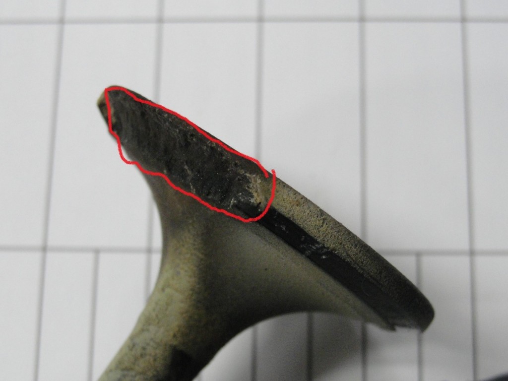
Burnt exhaust valve
Notice the area inside black this is burnt area of #5 exhaust valve.
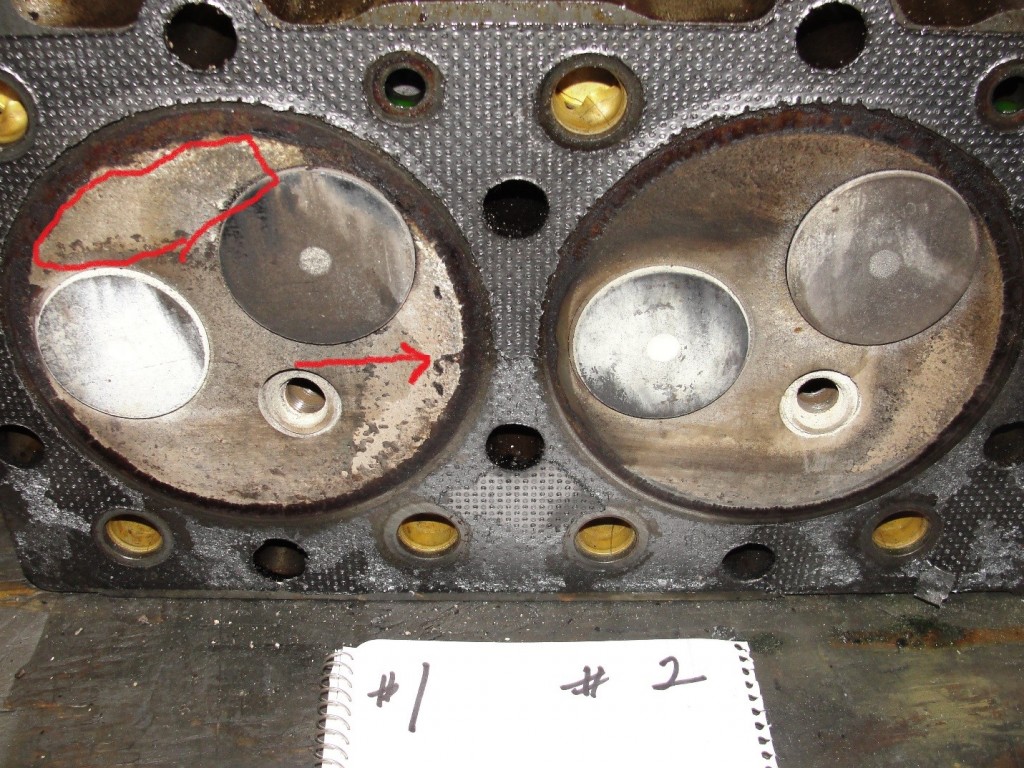
deposit build-up on cylinder head and exhaust/intake valve faces.
Notice the build-up of deposits inside red area and red arrow on cylinder head, exhaust and intake valve face.
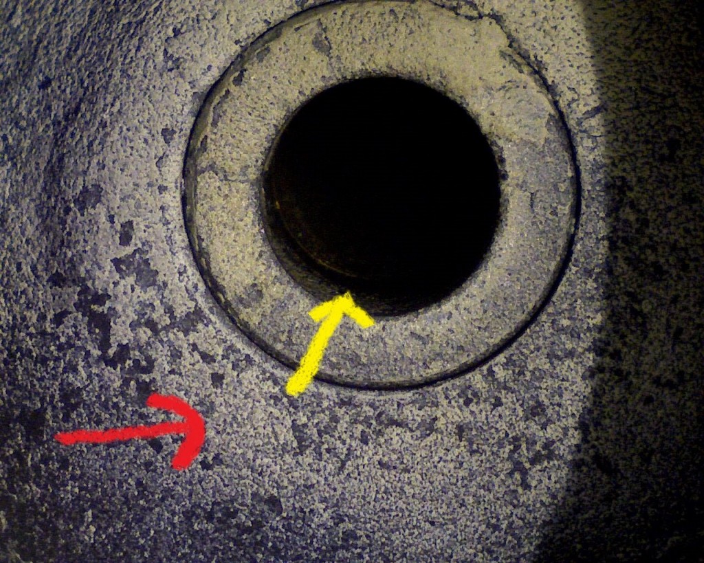
deposits inside exhaust valve guide and exhaust port
Notice the build-up of deposits inside exhaust valve guide yellow arrow area. Red arrow area is build-up of deposits in exhaust port area of cylinder head. This build-up of excessive deposits can cause valve to stick in valve guide.
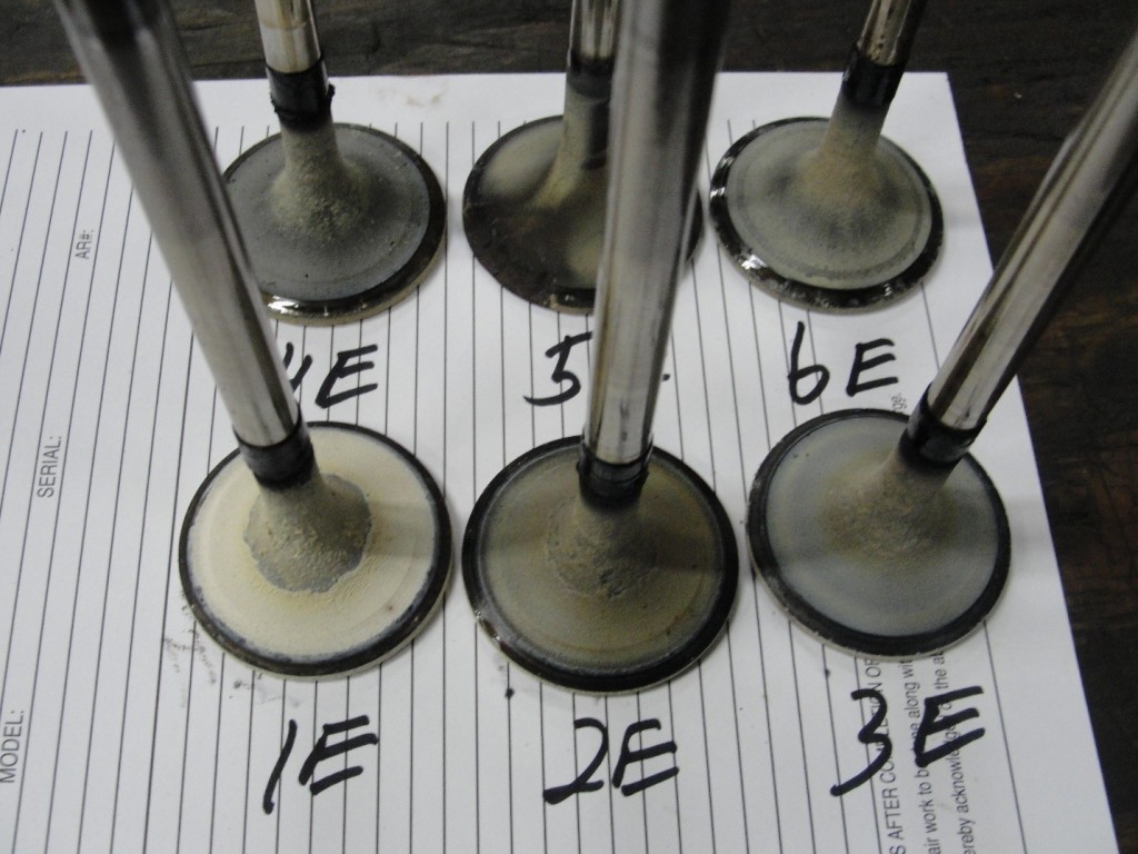
deposit build-up on exhaust valves
Notice the build-up of deposits on all exhaust valves this is excessive for the low hours on valves.
Excessive oil build-up on an engine exhaust valve stem
Notice the area at red arrow excessive oil build-up on valve stem all exhaust valves have this same build-up
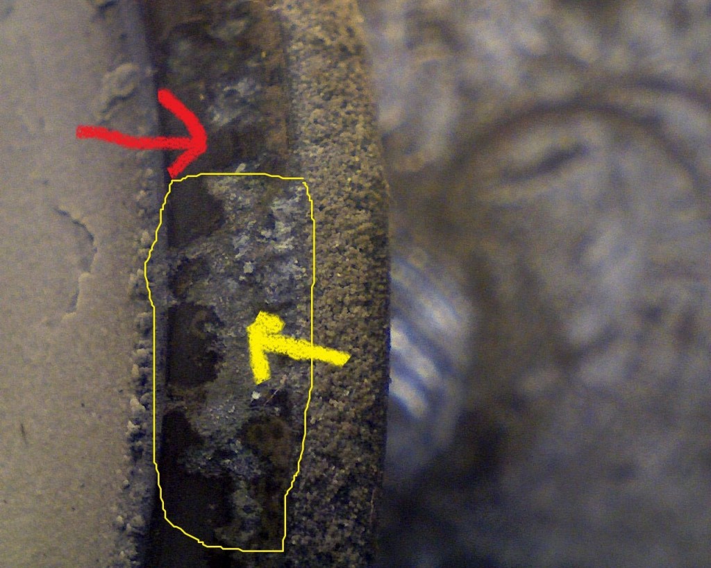
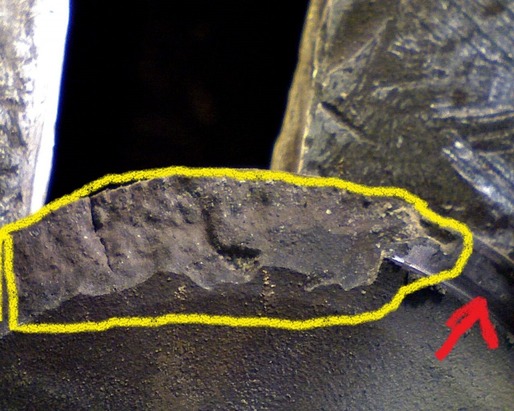
close up of deposits and damage to the valve face seat sealing area
Notice the deposits on exhaust valve face seat sealing area inside yellow and yellow arrow area. These deposits cause combustion gas leak paths that process to valve guttering/torching. Red arrow area is exhaust valve face seat sealing area. All exhaust valves have this same issue.
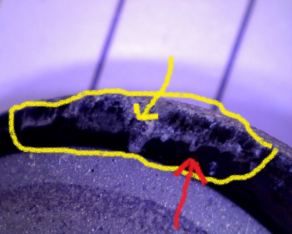
Close up of damage on the valve face seat sealing area
Deposits on exhaust valve face seat sealing area notice the area inside yellow. Red arrow area is valve face seat sealing area.
burnt exhaust valve
Burnt exhaust valve notice area inside red
engine valve guttering and torching from a hot combustion gas leak
Burnt exhaust valve notice area inside yellow. Red arrow area is valve face seat sealing area. The area inside yellow is due to hot combustion gas leak path causing valve guttering/torching.
Excessive oil deposit build-up on engine intake valves
Notice the excessive engine oil deposits in the red arrow area on all intake valves. This is excessive for the low hours on these valves.
excessive oil build-up on an engine intake valve
Intake valve notice the excessive engine oil deposits on valve all intake valves have this same excessive engine oil deposits build-up. With this excessive oil deposits build-up on intake valves in 100 hrs. would expect oil consumption to be excessive.
Exhaust valve damage
Notice the area inside red. Valve same failure mode as engine S/N G6X01029 exhaust valves, valve guttering/torching.
Notice area at red arrow excessive engine oil deposits build-up. Same excessive deposits build-up has engine S/N G6X01029. The black arrow area is the valve face seat sealing area.
build-up on valve face seat sealing area
Notice red arrow area same deposits build-up on valve face seat sealing area as engine S/N G6X01029 exhaust valves. Yellow arrow area is valve face seat sealing area.
valve face seat sealing area of a Cat Exchange Cylinder Head
Notice the area between the red arrows this is the valve face seat sealing area. Notice the width of sealing area this appears to be about 0.100 I like to have this at min. spec’s not max specs with new valves. If you are at min. side of specs have less surface area for deposits to stick/cling to causing leak path. This valve is out of Cat Exchange cylinder head.

Had [SEM] scanning electron microscopy analysis of deposits on exhaust and intake valves.

Elements that were in deposits.

CA – Calcium             New oil additive 1132-1384 PPM

ZN – Zinc                     New oil additive 290-358 PPM

P – Phosphorous       New oil additive 255-311 PPM

S – Sulfur                     In natural gas

O – Oxygen


C – Carbon                By product of combustion deposits

FE – Iron                    Liners and valves

CR – Chromium        Valves, top piston rings, valve stem plating

NI – Nickel                valves

K – Potassium          New oil and airborne

NA – Sodium           New oil and airborne

Deposits are due to burning excessive oil during the combustion process.

3306 engine S/N G6X01029 if this engine has not been re-rated to a new spec number operating this engine at 1250 RPM and 35% load is a concern. This engine per Cat test cell number 511 report engine is rated at 202HP @1800 RPM. A typical natural gas engine design will optimize valve lubrication at full load, but this can lead to excessive oil flow to the valves under low load conditions. Prolonged operation at low loads below the boost range of turbo can lead to increased oil consumption and a resulting build-up of deposits. Operation at low loads and low RPM causes low intake manifold pressures which can result in higher than normal oil lubrication of valves, rings and liners.

This engine cylinder head was built with no valve guide seals. With low load conditions this causes excessive oil between valve guide and valve stem.


Need to check intake manifold pressure with engine operation at its normal conditions. Per Cat natural gas 3306 engine performance data.


100% load                  75% load              50%load

Manifold pressure                   38.5 HG                     32.3 HG                  24.9 HG

Manifold pressure                    18.9 PSI                     15.9 PSI                  12.2 PSI

Cause of valve failure is deposits between exhaust valve face seat sealing area and valve insert seat sealing area due to engine burning excessive oil in the combustion process.